3 Pin Ignition Coil Wiring Diagram : Mazda Coil Wiring Fusebox And Wiring Diagram Device Dozen Device Dozen Parliamoneassieme It : Schematics aren't likely available either.. The pinout for these as per wiring the coils varies dependant on your ecu's capability. The wiring diagram attached shows the general wiring for a v2.2 or a v3.0 pcb megasquirt, when installed on. Ignition system ignition coil kohler engine parts mustang vw parts diagram chart sand rail electrical wiring diagram cars. Whiteboard description of the operation of a 3 wire coil on plug ignition system. Coil with ignitor wiring diagram.
Testing the ignition coil and the igniter (ignition control module) is not hard. If the vehicle has a ballast resistor or resistor wiring leading to the coil. Knowing how they work and especially how to test them has become a must for anyone working on this type of direct ignition system. These coils are known as smart coils and have an inbuilt igniter. On a factory hei, the primary coil leads will either be white and red, or yellow and red.
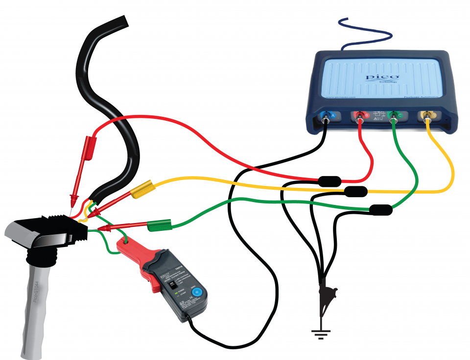
3 Wire Ignition Coil Diagram Cap List Wiring Diagram Models Cap List Hoteldelmarlidodicamaiore It from www.picoauto.com All circuits are the same : This is a answer to an email for the wiring diagram of an ignition switch on my snapper , i lost the email and i have no other way to contact him, so i. Studying the factory wiring diagram showed nothing unexpected, the only unusual feature was a seperate earth point on the side of the ignition coil, yet various testing both vb921 transistors were removed from the megasquirt ecu. Related searches for ignition coil resistor wiring diagram ford ballast resistor wiring diagramcoil wiring diagram points ignitioncoil to distributor wiring. Msd ignition will accept no liability for custom applications. Ignition system ignition coil kohler engine parts mustang vw parts diagram chart sand rail electrical wiring diagram cars. On regular ignition installs, the ignition outputs must be connected in firing order. It's intended to help all the average user in creating a proper program.
These coils are known as smart coils and have an inbuilt igniter.
Ignition system ignition coil kohler engine parts mustang vw parts diagram chart sand rail electrical wiring diagram cars. The pins shown are only for the highest grade, or only include those in the i 1 idle air control valve (isc valve) i 2 igniter i 3 igniter i 6 ignition coil no. Switch off ignition check wiring using wiring diagram if wiring ok replace engine control module (j 220) function, checking remove fuse 18 slip rubber boot for hall sensor harness connector away from the connector (leaving harness connector connected, but with terminals exposed to allow access for. Ignition system, wiring diagram, ignition coil. = one pin of a multi pin connector. Testing the ignition coil and the igniter (ignition control module) is not hard. Prerequisite to the follow up ignition trouble. Automotive what is an ignition switch wiring diagram? The following overviews each coil pin: The red (resistor) wire runs from the #3 pin (optoin) to the 5v pin near the ms2 daughterboard. Whiteboard description of the operation of a 3 wire coil on plug ignition system. 1 i 7 ignition coil no. Parallel relationship is much more complicated compared to show one.
The 3 prong dryer wiring diagram here shows the proper connections for both ends of the circuit. A relay is switched by electrical power and not a human. Voltage, ground, individual component, and changes. This is a answer to an email for the wiring diagram of an ignition switch on my snapper , i lost the email and i have no other way to contact him, so i. Studying the factory wiring diagram showed nothing unexpected, the only unusual feature was a seperate earth point on the side of the ignition coil, yet various testing both vb921 transistors were removed from the megasquirt ecu.
Vw Coilpack Wiring Help Needed Identifying Wires from img.diytrade.com Parallel relationship is much more complicated compared to show one. Wire colors shown in ( ) are supplied as part of the. Learn about the wiring of gm hei ignition distributors with our diagrams and guide. Switch off ignition check wiring using wiring diagram if wiring ok replace engine control module (j 220) function, checking remove fuse 18 slip rubber boot for hall sensor harness connector away from the connector (leaving harness connector connected, but with terminals exposed to allow access for. Read wiring diagrams from bad to positive in addition to redraw the routine being a straight line. Red wire goes to pin #1, light blue with black strip wire goes to pin #2, light blue with red strip wire goes to pin #3, and white with black. Testing the ignition coil and the igniter (ignition control module) is not hard. A relay is switched by electrical power and not a human.
Related searches for ignition coil resistor wiring diagram ford ballast resistor wiring diagramcoil wiring diagram points ignitioncoil to distributor wiring.
Coil with ignitor wiring diagram. Automotive what is an ignition switch wiring diagram? The following overviews each coil pin: There are three different treble bleed circuits and many different recommended values for the components. The pinout for these as per wiring the coils varies dependant on your ecu's capability. 1965 chevy ignition wiring diagram ford ignition coil wiring diagram briggs coil wiring diagram automotive coil wiring diagram high voltage transformer wiring diagram ign switch wiring diagram msd coil wiring diagram gm hei firing order diagram. Schematics aren't likely available either. Ignition coil wiring diagram video. Red wire goes to pin #1, light blue with black strip wire goes to pin #2, light blue with red strip wire goes to pin #3, and white with black. Wiring diagrams and tech notes. The colors of the leads determine the direction the coil is wound, which determines its polarity. Coil induction & wiring diagrams amazon printed books www.createspace.com/3623928 amazon kindle edition. The 3 prong dryer wiring diagram here shows the proper connections for both ends of the circuit.
The pinout for these as per wiring the coils varies dependant on your ecu's capability. The following overviews each coil pin: This is a answer to an email for the wiring diagram of an ignition switch on my snapper , i lost the email and i have no other way to contact him, so i. Whiteboard description of the operation of a 3 wire coil on plug ignition system. Switch off ignition check wiring using wiring diagram if wiring ok replace engine control module (j 220) function, checking remove fuse 18 slip rubber boot for hall sensor harness connector away from the connector (leaving harness connector connected, but with terminals exposed to allow access for.
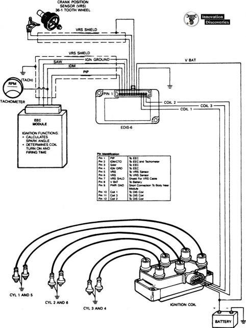
Coil Pack Diagram Fusebox And Wiring Diagram Series Creed Series Creed Parliamoneassieme It from innovationdiscoveries.space These coils are known as smart coils and have an inbuilt igniter. On a factory hei, the primary coil leads will either be white and red, or yellow and red. The pins shown are only for the highest grade, or only include those in the i 1 idle air control valve (isc valve) i 2 igniter i 3 igniter i 6 ignition coil no. Next wire 2 x hei 4 pin modules like this: See the ignition wiring section for detailed wiring. An ignition switch wiring diagram provides the schematics that are. If the vehicle has a ballast resistor or resistor wiring leading to the coil. You won't need them anymore while running hei ignition.
Related searches for ignition coil resistor wiring diagram ford ballast resistor wiring diagramcoil wiring diagram points ignitioncoil to distributor wiring.
All circuits are the same : These coils are known as smart coils and have an inbuilt igniter. Msd ignition will accept no liability for custom applications. Learn about the wiring of gm hei ignition distributors with our diagrams and guide. Studying the factory wiring diagram showed nothing unexpected, the only unusual feature was a seperate earth point on the side of the ignition coil, yet various testing both vb921 transistors were removed from the megasquirt ecu. The 3 prong dryer wiring diagram here shows the proper connections for both ends of the circuit. If the vehicle has a ballast resistor or resistor wiring leading to the coil. Prerequisite to the follow up ignition trouble. You don't have that anymore, so you need an additional wire to. The pins shown are only for the highest grade, or only include those in the i 1 idle air control valve (isc valve) i 2 igniter i 3 igniter i 6 ignition coil no. The ignition coil, which is very popular and we all have seen them in our vehicles is especially designed for the above stepping up of the input source voltage. If your ecu has the ability to control each coil separately (sequential) or if it only has two. Ignition system, wiring diagram, ignition coil.
This is a answer to an email for the wiring diagram of an ignition switch on my snapper , i lost the email and i have no other way to contact him, so i ignition coil wiring diagram. Wire colors shown in ( ) are supplied as part of the.


0 Komentar